Segmented Sphere Building 101
IntroductionNecessity is truly the mother of invention. It has always been my intent as an artist to let my pieces dictate the materials and processes used in their creation. This unpredictability keeps me keenly interested in my work. Whether it is book binding, metalworking, woodworking, or clock-making, my work has been a continual motivation to acquire new skills. As luck would have it, my current piece dictated the need for a large, hardwood sphere. I had no idea of how to proceed. After some research I decided that a lathe was not the answer, as it is limited in the size of sphere that can be turned. Besides, I didn't have the space or money for a lathe and all the needed tools. Ultimately I decided that stacked rings might do the trick. In an effort to minimize the amount of end grain, I increased the number of segments I would need for each ring from four (essentially cutting a ring from a frame), to eight. Eventually I realized that the glue lines, if built correctly, could represent latitudes and longitudes, as the purpose of this sphere was to become a floor globe. It was then that I decided on eighteen segments for each ring, and eighteen stacked rings. This was not an easy project but it was essential to the realization of this particular artwork. Since floor globes come in many different styles, I decided to write about building a hardwood sphere without the use of a lathe and let you, the reader, pursue the globe stand you would most enjoy. Geometry predicts a certain ease of construction, however, variables such as wood distortions and imperfect tool set-ups can introduce unpredicted results. Having said that, I have found that some inaccuracies are unavoidable and can often cancel each other out. Is my sphere a perfect sphere? I'm sure it's not but it does measure the same from pole to pole as it does from opposite sides of the equator. To the eye, this is a perfect sphere. Now, since I will be carving into the oceans and around the major land masses, I didn't bother sanding the surface to perfection. If you decide to undertake this project, understand that it will be long hours in the making. However, now that I have made one myself, I highly recommend it.
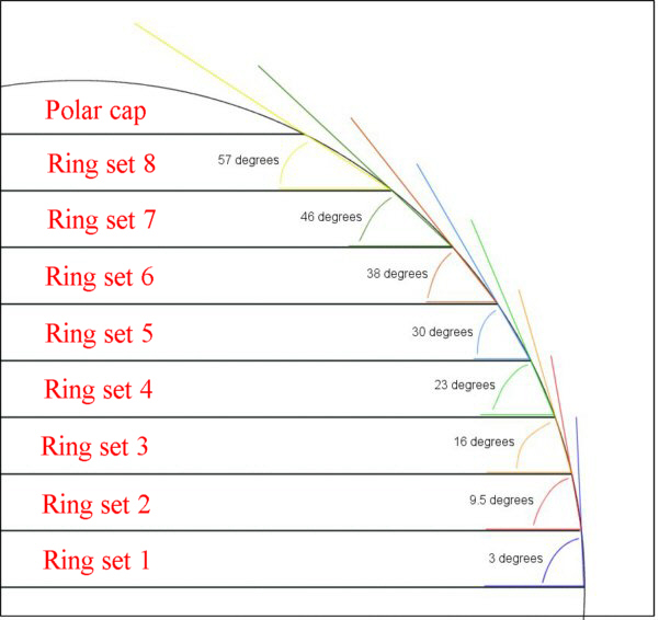
Step OnePlanning: The first step is to find the bevel angle for each ring. I drew up a double sized diagram and started measuring. By connecting the two points where the bottom and top of the ring intersect with the circle and extending that line out, the angle can be measured with an ordinary protractor.
figure 1: drawing for ring set bevel angles
When I did this I came up with the following angles which start with the center two rings and work toward the poles. Ring set 1; 3.0 degrees Ring set 2; 9.5 degrees Ring set 3; 16.0 degrees Ring set 4; 23.0 degrees Ring set 5; 30.0 degrees Ring set 6; 38.0 degrees Ring set 7; 46.0 degrees Ring set 8; 57.0 degrees
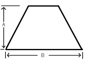
Step twoCreating the ring sets: Set your table saw blade to 90 degrees (to the table) as accurately as possible. To set your miter gauge to the proper angle, decide how many segments you want your rings to have and divide 180 by the number of segments. In my case that was 180 divided by 18 which equals 10 degrees. You may want to purchase an accurate miter gauge or a tool like the Mitermatic from Woodhaven.com which makes setting your miter gauge easier. When making a multiple segment ring, even the smallest inaccuracy will result in problems. For instance, if your miter gauge is set to 9.75 degrees instead of the needed 10 for an eighteen segment ring, that .25 degrees multiplied by thirty-six joints results in a gap of 9 degrees. If your segments fit with no gaps, the rest of the project will go very smoothly. Here's a tip: once you have your miter gauge set perfectly, don't change the setting until all the segments for both rings in a set have been cut. If the segment angles don't match from ring to ring, you'll be in for a lot of tweaking. Also, the state of your wood will have a great effect on the outcome. If each board is perfectly straight and flat (yeah right!), the cuts should be repeatable. Now, to figure the outside length of each segment I came up with this formula. Decide the outside diameter of ring set 1 (which will be the final diameter of your sphere before sanding), add one inch, multiply by Pi, and divide by the number of segments. By adding one inch to the diameter, you're giving the ring a bit more surface area. You'll need this for supporting the jig saw base as you make the cut. Also, keep in mind the thickness of your wood when deciding on the diameter of your sphere. I used six-quarter cherry, planed to five-quarter after gluing. Eighteen rings multiplied by their 1.25 inch thickness gave me the final diameter of 22.5 inches. It should be noted here that as you work your way towards the poles, each ring will have a steeper bevel, and as such, will need to have a greater "A" dimension. In effect, as you work toward the poles, each ring set will increase at "A" and decrease at "B" in order to create smaller and smaller diameter rings that can handle the increase in bevel angle for each ring set (see figure 1 for bevel angles).
figure 2: segment dimensions
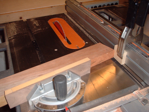
Cut enough segments for two rings, remember you're making two of each. Use the stop-block method on your table saw to get each segment exactly the same length (see photo). It is also very important to have your blade set as close to 90 degrees (to the table) as possible. Notice the hardwood fence attached to the miter gauge, the face is covered with fine sandpaper for a no-slip effect. Make the initial cut, then flip the board over , align with the stop-block, and make the next cut. Repeat until you have all the segments cut. Watch for wood particles collecting between your wood and the miter gauge fence, this can throw off the accuracy of your cuts.
figure 3: stop-block method
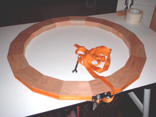
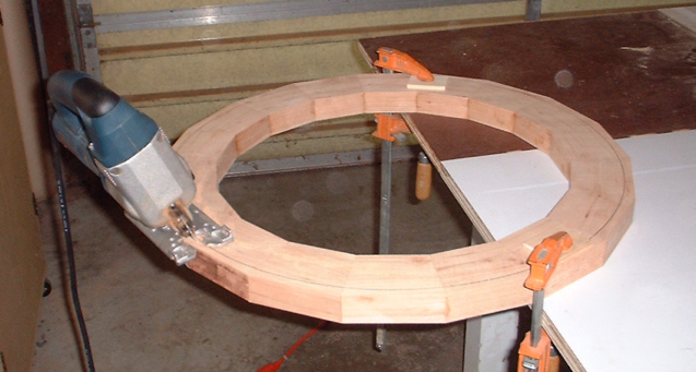
figure 4: A single ring, dry-clamped and ready for gluing.
The greatest challenge will be getting the longitude lines (or the joints between segments) to line up correctly when each new ring is added. The lines may not match, no matter how accurately your tools are set up. It will be a simple, albeit time consuming, matter of "tweaking" each new ring to match its mate. After gluing, flattening, cutting, and beveling (see steps 3 and 4 below) a ring, set it onto its mate (not the second ring of the set but the preceding ring onto which it will be glued). Mark any discrepancies and shave the troubled segment to fit. It may be necessary to readjust your miter gauge for this shaving-refitting process. Of course this must be done before the ring being tweaked is glued up, just dry clamp with a band-clamp to hold the ring together while comparing. The final result may not be perfection but it will be very close. Note: I used an assortment of colored pencils to make line-up marks on the inside of mating rings after tweaking. You wouldn't want to lose the line-up of a ring and it's mate. When all the segments line up and your satisfied with the fit, glue the segments together to form the ring. Be sure and apply glue to both surfaces of the joint, you will need it to be strong. Work quickly, you don't want the glue on the first segment to set while you're working your way around the ring. I used a band clamp, it worked quite well for this. Let the glue set for at least twenty-four hours.
Step threeFlattening the rings: There are two different methods for flattening the rings. Method 1If you own a drill press you may want to purchase a tool called the Safe-T-Planer by Wagner. This tool will save you from hand sanding/flattening the rings. It's safe, as the name implies, and effective. Here's a tip; feed the ring into the planer in a clockwise direction. This way the dust and shavings are directed back, away from you and the work piece. Otherwise this dust is directed towards and under the ring, raising it as you work. This makes for a never-ending planing job.
figure 5: The Safe-T-Planer chucked-up and doing its thang. The planed area in this photo looks coved but it's just an optical illusion (or my cheap digital camera). Compare the length/width ratio of this later ring to the ring in figure 4 above.
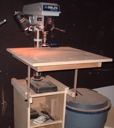
The table on my drill press wasn't near big enough so I built this nifty table with adjustable outboard supports. These supports stop the table from sagging during the planing process.
figure 6: shop-built drill press table
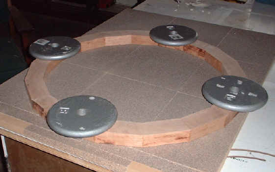
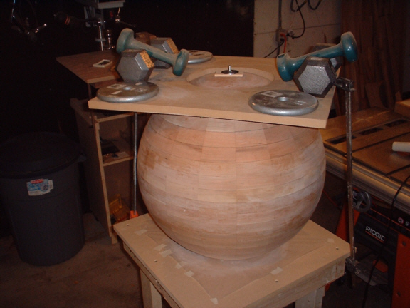
Method 2Find a flat piece of MDF or plywood large enough to accommodate your largest ring as it slides to and fro. Attach 40 grit sandpaper using contact cement. This is gnarly stuff so follow the directions carefully. Attach four barbell weights to the ring at equidistant points using sticky tack or another similar product. The trick here is to use something that removes from the wood easily, you'll be repeating this process often. Sanding the rings flat requires 25 back and forth strokes followed by 1/8th turn, followed by 25 strokes, followed by 1/8th turn, followed by.... Twice around on each side. The weights I used were 5 Lbs. each and helped exert equal pressure during the flattening process. It's labor intensive but not as difficult as it sounds, although, you may have arms like Popeye's by the time you're through. Obviously this method will take time...a lot of time. I think I worked the first three ring sets in this manner before I found the Safe-T-Planer.
figure 7: A single ring, ready for flattening
Why not just use a planer?Two very good reasons for not using a planer are: 1. Unless your sphere is quite small, you're going to have a tough time finding a planer large enough to accommodate your largest rings. My ring set 1 before jig sawing was just over 24", much too large for the average non-industrial planer. 2. No matter how you feed the ring into the machine, it will ultimately have to make its pass across the grain with unfavorable results. The ring might even fly apart inside the planer. Imagine what that would do to your planer knives.
Step fourCutting out the rings: Next, cut out the circular shape using a jig saw set at the correct angle. Cut close to, but not at, the mark. Be careful not to come any closer than 1/8". It takes a little more time at the sander but one little slip or bad area of tear-out and you would have to remake the entire ring. To find the appropriate diameter for each new ring, simply lay the previous ring, small diameter side down, on top of the ring to be marked. Line up the joints (longitudes) and trace. The small diameter of the previous ring becomes the large diameter of the new ring. Consider using a sliding T-bevel and protractor for setting the jig saw base to the correct angle.
figure 8: Cutting the ring from an octadecagon Note: In retrospect, I should have cut some material from the inside diameter of each ring, maybe using the same bevel as the outside cut. I could have made my finished sphere much lighter this way. However, be careful not to make the sphere wall too thin, especially if you plan to carve oceans and continents.
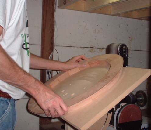
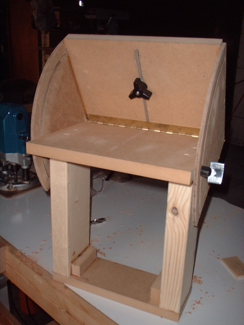
Step fiveCreating the bevel: The next step is to bevel the ring set to the desired angle. Double check your diagram and measurements before proceeding. I made a specially designed tilting table for my combo sander. For ring sets 7, 8, and the polar caps, you will need to make a sharper bevel than 45 degrees, which is the limit of most sander/table set-ups. Also, the tiny, weak, stock table that came with my sander was simply too small. Build something rigid, flat, and easily adjustable. Later in this article, where I describe the polar cap sanding procedures, you will get a better look at the table I built with the large tabletop removed. Sanding will take some time, be patient. I found it beneficial to sand right to the line and then slowly sand the line off. When you traced the previous ring's small diameter onto this ring, the mark laid outside the previous ring's diameter, and so must be sanded off. While sanding each new ring, keep its mate nearby for comparison. You don't want to sand the ring until it's too small. Consider starting with a 50 grit belt for speed, sanding past the mark with a 120 grit belt for greater control. Note: you'll need good lighting above your sander to clearly see the mark.
figure 9: Sanding the ring to the correct bevel and dimension
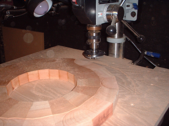
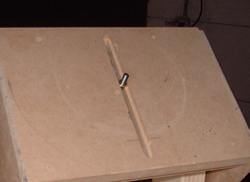
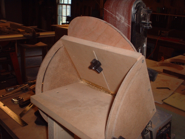
Forming the two pole discs presents a unique challenge. The poles should be cut from a solid board rather than segmented rings. This way any errors won't be magnified. For instance; any two longitudes that converge a little two quickly would come to a point before reaching the pole. By cutting a countersunk slot in my sanding table, I could project a bolt through the table that would hold the pole disc in place but allow me to simultaneously elevate the table and slide the disk into its new position. So, after sanding around the circumference, I slid the disc higher up and elevated the table to the next angle. Doing this six times gave me a pretty good arched cap. Note: I'm using the table in reverse when compared to figure 9 above.
figure 10: The pin/bolt projecting through the countersunk slot. This is the same table I used to sand/bevel the rings to the proper angle (figure 9) but without the large table-top attached.
figure 11: The tightening knob from the back of the table
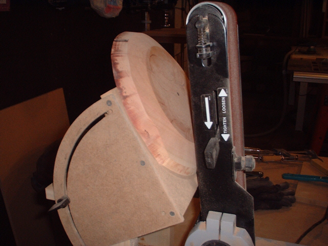
You should use hardwood for the upright supports and the lower brace for maximum rigidity. I found that the pine and MDF I used flexed a bit under the strain. Note: It would be best not to bolt the sander down while forming the polar caps, if the disc were to get pinched between the table and sander it could burn up the sander before you could get to the power switch. This did happen once while sanding and the sander just slid back enough not to jam. You might, however, place the sander on a no-skid pad. If you are making a globe, you will be needing axle holes in each pole. Drill a 1/4 inch hole in your board before cutting out the disc. You might even place a pin in this hole as a guide for cutting out the disc. These holes will be used for the sanding table pin. If you want a solid sphere (meaning no axle holes), simply don't drill the holes all the way through the top of the disc. You don't want the bolt/pin projecting out of the front of the disc while sanding anyway.
figure 12: Make sure there is enough disc projecting above the table to grab and turn.
figure 13: A polar cap being sanded
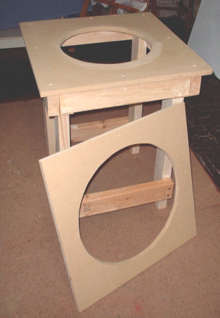
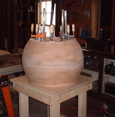
Step sixGlue up: Gluing it up required that I knock together a special table. I made three interchangeable tops for the table, each with a progressively smaller hole. As you glue each new ring set to the sphere, your clamps will move closer to the center of the table, requiring a smaller hole about every three ring sets.
figure 14: The sphere gluing table, two of the table tops can be seen in this photo.
When gluing up, I added only one ring at a time. I started with ring set 1, giving the glue plenty of time to cure. After which I added one ring from ring set 2 and let it cure, flipping the sphere over and adding the second ring in the set and letting it cure. It will take a few days to get all the way to the poles but I think you'll agree that after all this work, small steps give emotional security.
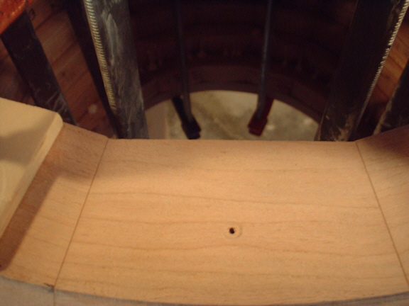
figure 15: The first ring of set six glued and clamped It may be prudent to use the alignment-pin method for gluing. After aligning and dry- clamping, drill all the way through the top ring (as close to the I.D. as possible) and into the next to about 1/4". After removing the top ring, tap in a finishing nail and clip it off as short as possible. Do this in three places around the circumference and you won't have to worry about the rings sliding while you clamp (and believe me, they will). Simply apply the glue to both surfaces, place the the one ring on top of the other and align it until it drops onto the pins. In this picture, you can see the resulting hole left by drilling through the top ring. Note: the hole doesn't appear to be very close to the I.D. but, because of the bevel, the hole in the ring underneath is very close to the inner edge. If it were drilled any further in, it would miss the ring underneath all together.
figure 16: hole placement for pin
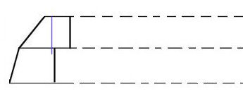
figure 17: Cross-section of two rings being pinned. The blue line represents the drilled hole. The nail is tapped into the bottom ring and then clipped off short.
The last set of rings and the pole caps will require that you not drill all the way through the top ring. The holes will get too close to what would be the surface of the finished sphere and in the case of ring set 8, would have to be drill into the bevel itself. Instead you will have to drill into just the bottom ring, set and clip the pins, align as best you can, and tap the top ring down onto the pins.
As for gluing on the polar caps, it's a simple matter of bolting them on with a length of threaded-rod. Glue-up one cap at a time and place one of the table-tops over the cap and weight it to hold the edges down while drying. Note the use of the fender washer and a short length of pine lattice for padding.
figure 18: Gluing the first polar cap
figure 19: A shot from underneath the table, a length of 2x4 is being used to span the gap in the table for the first polar cap.
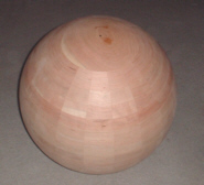
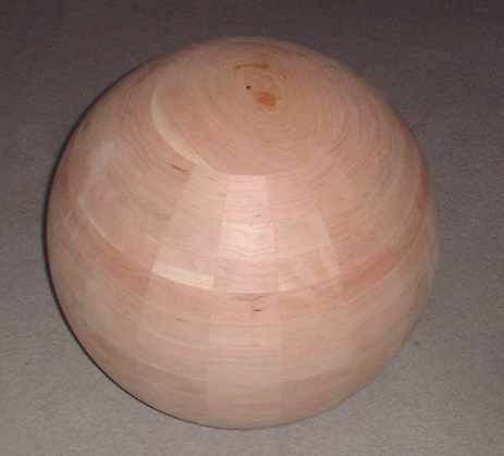
Step sevenSanding: The finished sphere has eighteen longitude lines and eighteen latitudes. I thought about going with thirty-two longitudes but that seemed a bit overwhelming. It measures 22.5" in diameter, that's 18 rings times 1.25" thick (per ring) after planing and sanding. Here, the sphere has been glued-up, the corners knocked down with a handmade scraper cut to the proper radius (see picture below), and sanded. I began the sanding process by further knocking down the joints between rings with my random-orbital sander, followed by about an hour of sanding from pole to pole. Continue sanding until the surface ripples are diminished or disappear altogether. You may want to make a cardboard template with an arc of the proper radius for checking the surface curvature while sanding.
figure 20: The finished sphere
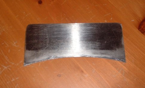
figure 21: hand made hand scaper Scrapers such as this one are best made from tool-steel. I used an old crosscut saw for the raw material. Make sure you give your scraper a good "hook". Detailed directions for making a scraper can be found by doing a simple web-search.
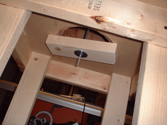
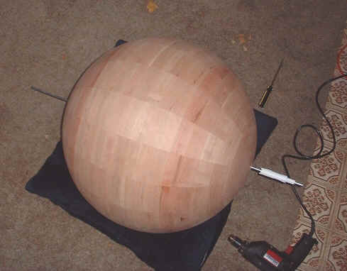
LastlyDrilling the poles: In order to use bronze bearings at the poles you will need to drill the proper size hole (dependant on the size of bearings you will use). I purchased the correct hole-saw and simply replaced the drill bit with a long enough piece of 1/4" steel rod. By feeding the rod all the way through both poles, I was able to make the cuts so that the pole holes would line up with each other. Note: I cut the first hole as deep as possible without going all the way through. If I had cut all the way through, I would not have had that 1/4" hole to guide me when cutting the second pole. With the first hole cut most of the way, the cut was deep enough to guide the hole-saw for the final cut without the need for the 1/4" steel rod.
figure 22: drilling the poles
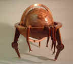
The finished artwork, click image for details
|