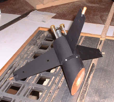
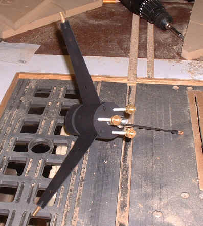
This is a three-vane spider and secondary holder. The adjustment screws were designed into the spider main body assembly for easier accessThe spider vanes were cut from thin sheet-metal. I clamped three layers of sheet-metal between two pieces of hardboard by drilling through all and bolting. I then cut the rough shape with a metal-cutting blade in my jig saw. After cutting, the assembly was sanded to size on a combination belt / disc sander.
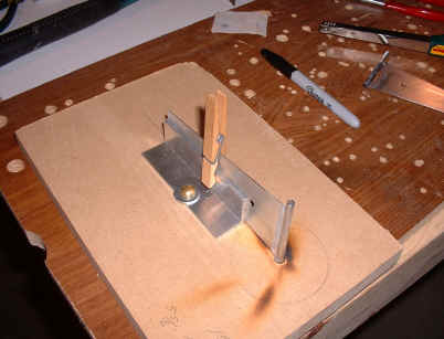
This homemade fin jig was just the ticket for soldering the vanes.
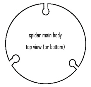
1/4" steel rod was soldered to the ends of each fin in order to slide into 1/4" holes drilled at 120 degree intervals in the main body of the spider. These holes were then sawed into from the sides so that the vanes could simply slide down into the main body. I used 2-ton epoxy to glue the fins in place when the time came. The following rough drawing illustrates how the main body should look after the drilling and sawing.
I should mention that I was unable to find 2" dowel for building this spider. This size was necessary to properly hold the 2.1" minor axis secondary. I solved this by gluing up a block of oak about 3"x3"x8" and cutting it down on the table saw into an octagonal shape. This was sanded on the combination sander until round and two inches in diameter. It seems a bit labor intensive but it really wasn't. The next step was to cut the heads off a few brass bolts, saw a slot in each, and solder them to the outside ends of the vanes. In retrospect, I should have used coupling nuts instead of the brass bolts. Rather than bending the vanes until they slide into the OTA (possibly damaging the spider), and ultimately through holes drilled in the tube, I should have simply designed the spider so that the coupler nuts (soldered to the vane ends) would be about 1/2" from the inside of the tube. This way, bolts could be threaded into the spider from outside the OTA, adjustments made as necessary to center it in the tube, and to allow for offset adjustment.
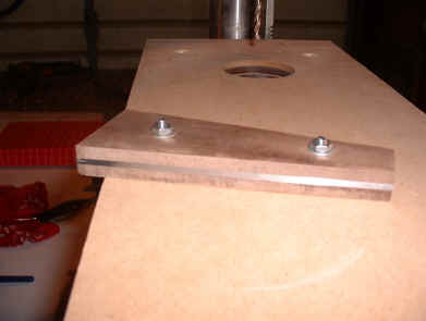
A center hole was drilled to accept the secondary holder bolt as were three holes for the collimation bolts. I was able to cut threads for the collimation bolts right into the oak itself. It is a very hard wood and took the threads well. Just round-over a length of threaded rod, hold the rod with vice-grips and thread it into the holes. A little oil will help and use a slow "thread in a little, turn back out, thread in a little more" approach. The collimation bolts are simply three lengths of 1/4-20 threaded rod, rounded at the holder end. 1/4-28 knurled nuts (brass) were then forced onto the other ends. This was necessary to ensure the nuts would not twist on or off the bolts. The secondary holder is simply another piece of the oak cut at 90 degrees for the bottom and 45 degrees to accept the secondary. A 1/4 inch hole was drilled down the center (before the 45 degree cut) and then widened a little larger than the 1/4 inch bolt head. I actually used an acorn nut, drilled through and threaded onto a length of 1/4" threaded rod so that the round end of the acorn faced towards the length of rod. This helped the holder to pivot evenly when turning the adjustment screws on the spider. This bolt slides through the secondary holder and through the spider main body, emerging out the back. Slip on a compression spring, a washer, and finally, a nut. Thread your collimation bolts through the main body until they force the holder away from the main body about a 1/4 inch or so. This distance will vary; you won't know the final distance until you collimate your scope. All the hardware was then removed from the spider and holder so that they could be painted flat-black.
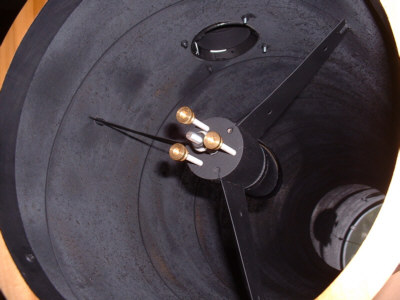
The spider installed in the tube
I should have painted the collimation hardware flat black but it just looks too darned cool in brass!
|